


Etching and Forming
1. Introduction
- We produce aluminum electrode foils mainly for aluminum electrolytic capacitors.
- Two types of aluminum electrode foils are used in aluminum electrolytic capacitors as anode and cathode foils.
- Electrode foil plays the role of dielectric in aluminum electrolytic capacitors, and therefore, a larger surface area is required (See Product Applications).
- Our aluminum electrode foil has a larger surface area by etching and a dielectric film by Forming.
2. Surface area expansion by etching
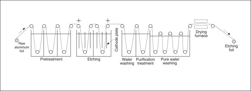
Etching is a technique to dissolve the surface of aluminum foil in order to increase the surface area of aluminum foil of the same projected area.
When etching metals, chemical corrosion using acid or alkali is generally used. However, we use electrochemical etching from the viewpoint of efficiency and control of area expansion.
Electrochemical etching increases the surface area of aluminum foil more than 100 times for low-pressure applications and more than 20 times for high-pressure applications, compared to
the raw aluminum foil.
Figure 1 is a simplified diagram of the etching process.
Etching is a pretreatment of aluminum foil to uniform the surface condition by first degreasing the foil and removing the natural oxide film. Chemical or electrolytic cleaning using acid, alkali, or organic solvents is generally used, followed by a thorough rinse.
After pretreatment, etching is performed to dissolve the aluminum foil surface. Etching is performed by applying electricity in an etching solution. Chloride solutions such as hydrochloric acid and salt are commonly used as etching solutions. There are many factors that affect etching results, including the temperature, concentration, and pH of the solution, the density and amount of current applied, and the structure of the electrode to be energized.


There are two types of etching: AC etching using AC current and DC etching using DC current.
Figure 2 and Figure 3 show the structure of each etching process.
In AC etching, etching starts and stops each time the polarity of the alternating current changes, resulting in a structure with a large number of small pits. Therefore, although AC etching is excellent in expanding surface area, the size of the pits is very small, and when dielectric film is formed in the Forming process described below, the pits are buried (clogged) by the Forming film in the high voltage range, and the expanded surface area cannot be utilized. Therefore, AC etching is used for low-voltage anode and cathode foils with thin film thickness.
In DC etching, once etching starts, etching proceeds in a depth direction, forming an aligned tunnel-like structure. Since the pits are larger in diameter and longer than those of AC etching, it is less likely to fill the pits even when generating dielectric films in the high voltage range, and is used for anode foils with thicker film thicknesses for medium and high voltage applications.
After etching, post-treatment is performed to remove impurities such as aluminum powder and chlorine ions generated during etching. The foil is then thoroughly rinsed with pure water,
dried, and rewound.
The foil surface immediately after etching is highly reactive to moisture, and post-treatment and water rinsing are used to control and stabilize the reaction. Despite the
stabilization process, if the etched foil is stored in an excessively hot and humid environment, not only will its characteristics not be fully demonstrated, but it may also generate
heat due to the reaction with moisture. Careful attention should be paid to storage.
3. Generation of dielectric film by Forming
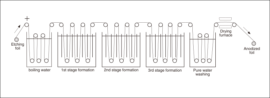
The Forming Process forms the oxide film that serves as the dielectric of the aluminum electrolytic capacitor. An oxide film is formed by continuous anodic oxidation of an etched foil
with an enlarged surface area by etching.
Figure 4 shows a simplified diagram of the Forming Process.
Anodic oxidation is performed in a chemical solution with the etched foil as the anode. Anodic oxidation of aluminum (anodic oxide film formation) is generally achieved by anodizing in
Forming electrolytes such as sulfuric acid, chromic acid, and oxalic acid. However, an anodic oxide film is porous and thick, making it unsuitable as a dielectric film for aluminum
electrolytic capacitors.
Therefore, we anodize anodic oxidation in near-neutral chemical solutions such as ammonium borate, ammonium phosphate, and ammonium organic acid. The resulting film is thin and has
high dielectric strength, making it suitable as a dielectric film for aluminum electrolytic capacitors.
Forming can be done in a single-step or multi-step method. In the multi-step method, the anodizing voltage is increased in stages by dividing the anode oxidation into several stages, so that safe and efficient anode oxidation up to the target voltage can be expected. In the case of high-voltage anode oxidation, boiling in pure water before anode oxidation forms a pseudo-behmite film (AlOOH・H2O) on the foil surface to obtain a crystalline film with high withstand voltage, while at the same time reducing power consumption and speeding up the anode oxidation process itself. Finally, the foil is anodized until the leakage current is sufficiently low, rinsed, dried, and rewound. This completes the electrode foil for aluminum electrolytic capacitors.